解析プロジェクトの準備
Prepare an analysis project
『解析プロジェクト』では、
風況シミュレーションの対象領域となる計算格子を3Dシーン上で作成し、
各種パラメータを設定して風況解析ソルバーを実行します。
In the "analysis project",
you can create a computational grid on the 3D scene that is the target area for the wind simulation,
then set various parameters, and execute a wind analysis solver.
以下の手順で、解析プロジェクトを準備します。
Prepare an analysis project by the following procedure.
地形・物体データの準備
Preparing terrain and object data
風況シミュレーションの対象領域を設定するため、
Airflow AnalystはGISデータを基に地形に沿った計算格子を生成します。
その内部の、建物などの障害物が存在する格子点を、格子マスクとして登録できます。
シミュレーションに使う地形や物体のGISデータとして、以下のような形式が利用可能です。
なお、これらのデータには空間参照の設定が必要です。
To specify a target area for the wind simulation,
Airflow Analyst generates a computational grid over the terrain by GIS data.
Grid points within the grid where obstacles like buildings exist can be registered as grid mask.
The following formats are available as GIS data of the terrain or obstacles for simulations.
For these types of data, spatial reference settings are required.
利用可能な地形データ
Available terrain data
- 標高メッシュデータ
- Elevation mesh data
標高メッシュデータは、地形の標高をセル値として格納したラスターデータです。
GeoTIFF形式のみ利用できます。
標高値はメートル単位であることが必要です。
Elevation mesh data is the raster data that stores terrain elevation as each cell value.
You can use the GeoTIFF format as the terrain data.
Elevation values must be in meters.
- TINデータ
- TIN Data
TINデータは、地形の起伏を不規則な三角形の集合体で表現します。
Esri TIN形式を利用できます。
TIN (Triangulated Irregular Network) data expresses terrain undulations with a collection of irregular triangles.
You can use the Esri TIN format as the terrain data.
利用可能な物体データ
Available object data
- 2Dポリゴン・フィーチャークラス
- 2D polygon feature classes
物体の平面形状を示す2Dのポリゴン・フィーチャークラスは、
物体の高さを示す数値型フィールドがあれば、格子マスク判定に利用できます。
物体位置における地面の標高は、数値型フィールドで指定できます。
フィールド指定がない場合は、地形データから標高を取得します。
ピロティ、庇、高架などのように地面から離れている構造物については、
地面からのオフセット距離を数値型フィールドで指定できます。
2D polygon feature classes representing planar shapes of objects can be used for the grid mask judging
if they have a numeric field storing height values of the objects.
The elevation of the ground at each object position can be specified in a numeric field.
Without the field, the elevation will be taken from the terrain data.
As for structures above the ground like pilotis, eaves, elevated roads, etc.,
you can specify offset distances from the ground in a numeric field .
- 3Dソリッドモデルのマルチパッチ・フィーチャークラス
- Multipatch feature classes containing 3D solid models
複雑な立体の構造物については、
外部の3D編集ソフトウェアで3Dモデルデータ(.dae形式)を作成し、
ArcGISでマルチパッチ・フィーチャークラスを作成してデータを取り込む必要があります。
なるべく完全に閉じたソリッドモデルのマルチパッチ・フィーチャーを用意してください。
For complex 3D structures,
you need to build 3D model data (.dae format) with external 3D authoring software,
and create multipatch feature classes with ArcGIS to import the data.
Multipatch features should be completely closed solid models.
- 3Dサーフェスモデルのマルチパッチ・フィーチャークラス
- Multipatch feature classes containing 3D surface models with open bottom
底面が無い3D形状(サーフェスモデル)データでも、側面に空隙がなければ格子マスク判定が可能です。
It is possible to use 3D surface model data without bottom faces for the grid mask judging
if there is no gap on the side.
物体種別コード
Object type code
物体データとして使用するフィーチャークラスに整数型のフィールドを作成し、
下表に示す「物体種別コード」をフィーチャー毎に指定します。
フィーチャーの内部にある格子点にこのコードが与えられ、風の挙動はその値によって変化します。
物体の外側の格子点には、自由に空気が流れる空間として"0"が自動的に割り当てられます。
シミュレーションに影響させたくない物体は、"0"を指定しておけば空間と判定されます。
Create an integer field in the feature class to be used as object data,
and set an "object type code" value shown in the following table for each feature.
These codes will be assigned to grid points within the features, and the behavior of the wind changes according to them.
"0" are automatically assigned to grid points on the outside of the features as free flowing spaces.
For features that you do not want to use in the simulation, set "0" so that they will be judged to be spaces.
| 物体種別コード |
意味 |
| Object Type Code |
Meaning |
| 0 |
空間
Spaces
|
| 1 |
障害物 (風を通さない物体)
Obstacles
|
| 2 |
透過壁 (樹木など風を一部通す物体)
Permeable objects
|
| 5 |
拡散源 (拡散物質を放出する領域で、風の流れには影響を与えない)
拡散計算で使用します。
Diffusion sources
(A region that emits diffusion material, not affect the airflow)
Used only in diffusion mode
|
3Dシーンの準備
Preparing a 3D scene
ArcSceneの起動・レイヤー追加
Launch ArcScene and add layers
- ArcSceneを起動し、シーンドキュメントを開きます。
- Launch ArcScene and open a scene document.
- 3Dシーンには、WGS84相当の測地系に準拠する、メートル単位の空間参照を設定しておいてください。
- For the 3D scene, set a spatial reference of the meter unit that conforms to a geodetic system equivalent to WGS84.
- 地形や物体のGISデータを3Dシーンにレイヤーとして追加します。
格子生成の際に、地形レイヤーは1つだけ利用できます。
物体レイヤーは複数利用できます。
それぞれのレイヤーの空間参照は、3Dシーンの空間参照と同じか、変換可能である必要があります。
- Add GIS data of the terrain and objects to the 3D scene as layers.
Only one terrain layer can be used for grid generation.
Multiple layers of objects can be used.
The spatial reference of each layer must be the same or convertible to the spatial reference of the 3D scene.
- 各レイヤーのプロパティで、3D表示のための各種設定をしておいてください。
- In each layer's property, modify settings for 3D visualization.
解析プロジェクト
Analysis project
解析プロジェクトを作成し、風況解析に必要な計算格子などのデータを準備します。
それぞれの機能は[Airflow Analyst 解析]ツールバーから実行します。
Create an analysis project, and prepare various data such as a computational grid required for wind analysis.
You can call each function from the [Airflow Analyst - Analysis] toolbar.
解析ツールバー [解析プロジェクト]メニューの各種コマンド
Commands in the [Analysis Project] menu on the Analysis toolbar
- [新規]
- [New]
解析プロジェクトを新規作成します。
Create a new analysis project.
- [開く]
- [Open]
解析プロジェクトファイルを選択し、解析プロジェクトを再開します。
Select the analysis project file to resume an analysis project.
- [保存]
- [Save]
現在の解析設定を解析プロジェクトファイル(.afa)に保存します。
Save the current analysis settings in an analysis project file (.afa).
- [名前を付けて保存]
- [Save As]
現在の解析設定を別の解析プロジェクトファイルに保存します。
Save the current analysis settings in a separate analysis project file.
- [プロパティ]
- [Properties]
解析プロジェクトのプロパティダイアログボックスを表示します。
Open the Analysis Project Property dialog box.
- [閉じる]
- [Close]
解析プロジェクトを終了します。
Finish the analysis project.
- [オンラインヘルプ]
- [Online Help]
Airflow Analystのオンラインヘルプを表示します。
Launch the Airflow Analyst help website on the Internet.
- [Airflow Analystのバージョン情報]
- [About Airflow Analyst]
Airflow Analystのバージョンやライセンスの情報を表示します。ライセンスの登録もこちらです。
Display version and license information of Airflow Analyst. You can also update your license here.
解析プロジェクトの新規作成
Creating an analysis project
- 解析ツールバーの[解析プロジェクト > 新規]をクリックします。
- On the Analysis toolbar, click [Analysis Project > New].
- 風況解析ソルバーが複数種類インストールされている場合は、
ソルバータイプ選択ダイアログボックスが表示されます。
使用するソルバーの種類を選択してください。
利用可能なソルバーの種類は、エディションやバージョンによって異なります。
- If more than one type of wind analysis solver is installed,
the Select Solver Type dialog box will be displayed.
Choose the solver type that you want to use.
The available types depend on the edition and version.
RC-GISは、地表面や構造物周辺の風環境解析に最適化された数値流体力学(CFD)ソルバーです。
RC-GIS is a Computational Fluid Dynamics (CFD) solver optimized for wind environment analysis around the ground surface and structures.
- RC-GIS 大気安定度対応 (RC-GIS-ATM)
- RC-GIS with Atmospheric Stability (RC-GIS-ATM)
RC-GIS-ATMは、流入境界条件に加え、大気安定度の設定が可能なRC-GISです。
RC-GIS-ATM is a RC-GIS solver that can set atmospheric stability, in addition to the inlet boundary condition.
|
- 格子タイプ指定ダイアログボックスで、格子タイプを指定します。
- In the Select Grid Type dialog box, select the grid type.
- 単焦点(頂部平面)格子
- Single Focus (Flat Top) Grid
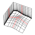
水平方向の格子は、格子の基準点を中心として、指定した間隔で広がっていきます。
The horizontal grid extends at specified intervals around the grid focus point.
鉛直方向の格子は、安定した計算に最適な間隔となるよう自動的に設定されます。
地表面の近くでは狭く、上方になるほど広くなります。
格子の最上面は、どの格子点も同じ高さで平らになります。
The vertical grid spacing is automatically optimized for stable calculation.
The spacing is small near the ground and widened above.
At the top of the grid, every grid point is level with the same height.
- 単焦点(頂部起伏)格子
- Single Focus (Raised Top) Grid
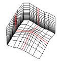
水平方向の格子は、単焦点(頂部平面)格子と同様です。
The horizontal grid is the same as Single Focus (Flat Top).
鉛直方向の格子間隔は、数値指定により調整できます。
各K層は地表面と平行になります。
格子の最上面は、地形に沿って起伏します。
The vertical grid spacing can be arranged by numerical values.
Each K section is parallel to the ground.
The top surface of the grid relieves along the terrain.
- カスタム間隔格子
- Custom Spacing Grid
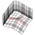
I, J, K方向の格子間隔を数値で任意に設定できます。
格子の最上面は、地形に沿って起伏します。
The grid spacing in the I, J, and K directions can be set arbitrarily by numerical values.
The top surface of the grid relieves along the terrain.
- 関心領域格子
- Area Of Interest Grid

任意の領域に特定の格子間隔を適用したい場合に選択します。
関心領域を示すポリゴンフィーチャーレイヤーが必要です。
I、J方向の格子間隔はポリゴンフィーチャーの数値フィールドから取得します。
ポリゴンの矩形範囲が互いに干渉する場合は、より小さい間隔値が採用されます。
K方向の格子間隔は数値で任意に設定できます。
格子の最上面は、地形に沿って起伏します。
Select this type when you want to apply specific grid spacing to any area.
It requires a polygon feature layer to indicate the area of interest.
The spacings in the I and J directions are obtained from the numeric field of polygon features.
If the rectangular areas of polygons interfere with each other, a smaller spacing value is used.
The spacing in the K direction can be set arbitrarily by numerical values.
The top surface of the grid relieves along the terrain.
|
- 作業用のディレクトリに、新規解析プロジェクトファイル(.afa)を保存します。
- Create a new analysis project file (.afa) in the working directory.
プロジェクトファイルのあるディレクトリが作業ディレクトリとなります。
シミュレーションに必要なデータファイル群は、全てこの作業ディレクトリに出力されます。
シミュレーションのケース毎に別途作業ディレクトリを作成してください。
Airflow Analystは規定のファイルが同一作業ディレクトリに存在することを前提に処理するので、
ファイルの削除、移動、名前変更には注意が必要です。
また、格子サイズ等によってはファイルサイズが巨大になるため(数十GB)、
作業ディレクトリは十分に空き容量のあるドライブに作成してください。
The directory where the project file exists is the working directory.
All data files necessary for the simulation are output to this directory.
Create a working directory separately for each simulation case.
Since Airflow Analyst treats the prescribed files as they are in the same working directory,
care must be taken when deleting, moving, and renaming the files.
Also, depending on the grid size etc., the files tend to become huge size (tens of gigabytes),
so create the working directory on a drive with sufficient free space.
- 解析プロジェクトの作成に成功すると、解析ツールバーの各種機能が有効になります。
- If the analysis project has been created successfully, various functions on the Analysis toolbar will be available.
解析プロジェクトのプロパティ
Properties of an analysis project
[解析プロジェクト > プロパティ]をクリックすると、
解析プロジェクトのプロパティダイアログボックスが表示されます。
Click [Analysis Project > Properties]
to display the Analysis Project Properties dialog box.
- [解析プロジェクトファイル]
- [Analysis Project File]
現在開いている解析プロジェクトファイルです。
The analysis project file currently open.
- [作業ディレクトリ]
- [Working Directory]
現在使用している作業ディレクトリです。
The folder currently used as the working directory.
- [ソルバータイプ]
- [Solver Type]
この解析プロジェクトで使用する風況解析ソルバーの種類です。
途中で変更できません。
The type of the wind analysis solver used in this analysis project.
It cannot be changed in the middle.
- [ソルバー]
- [Solver]
この解析プロジェクトで使用するソルバーです。
同種の別のソルバーがインストールされていれば、ソルバーを変更できます。
利用可能なソルバーは、エディションや製品バージョンによって異なります。
The solver used in this analysis project.
If another solver of the same type is installed, you can change the solver.
The available solvers depend on the edition and the product version.
- [格子タイプ]
- [Grid Type]
この解析プロジェクトで使用する計算格子の種類です。
途中で変更できません。
The type of the computational grid used in this analysis project.
It cannot be changed in the middle.
- [格子の鉛直方向の計算を省略する]
- [Simplify vertical coordinate calculation]
格子点数が多い場合、このチェックボックスをオンにすれば、格子表示の際に時間のかかる鉛直方向の格子座標計算が省略されます。
ソルバー実行前の解析用データファイル群の出力時には、設定にかかわらず省略せず計算が行われます。
If the number of grid points is large, selecting this check box omits time-consuming calculation of vertical grid coordinates for grid display.
When exporting the analysis data files before run the solver, the calculation is performed at any cost.
Copyright (C) 2020 Environmental GIS Laboratory Co.,Ltd. All rights reserved.