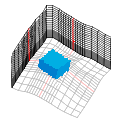
計算格子の作成
Create a computational grid
以下の手順で、気流解析の対象範囲となる計算格子を作成します。
Follow the steps below to create a computational grid that is the target area for an airflow analysis.
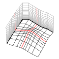
計算格子の生成
Generate a computational grid
- リボンの解析タブの格子グループにある
[格子位置]ツールをクリックします。
- On the Analysis tab on the ribbon, in the Grid group,
click the [Grid Position] tool.
- マウスカーソルでシーン上の地形または物体フィーチャをクリックすると、その位置に格子が生成されます。
- On the scene, click the terrain or object feature with the mouse cursor to place a grid.
- 何もない空間をクリックしても格子は生成されません。
- Clicking on space does not create a grid.
- 格子生成後には、このツールで格子の位置を変更できます。
- After creating the grid, you can change the position with this tool.
[計算格子設定]ダイアログボックスの表示
Open the [Grid Settings] dialog box
リボンの解析タブの格子グループにある
[格子設定]をクリックすると、
計算格子設定ダイアログボックスが表示されます。
On the Analysis tab on the ribbon, in the Grid group,
click [Grid Settings]
to open the Grid Settings dialog box.
位置指定
Location settings
計算格子設定ダイアログボックスの[位置]タブで、
格子の位置や地形を設定します。
On the [Location] tab in the Grid Settings dialog box,
set the position and terrain of the grid.
- 格子基準点と流入風向
- Grid reference point and inflow direction
- [経度]、[緯度]
- [Longitude], [Latitude]
格子の基準点の地理座標を経緯度で設定します。
Enter the geographic coordinates of the reference point of the grid with longitude and latitude.
- [標高]
- [Altitude]
デフォルトでは、地形データの標高に沿って格子が生成され、
その中の最低標高がこの欄に表示されます。
格子の底面を上下に移動したい場合は、この欄の数値を変更します。
By default, the grid is generated along the elevation of the terrain data,
and the lowest elevation in it is displayed here.
If you want to move the base plane of the grid up or down, change the value in this box.
- [流入風向]
- [Inflow direction]
流入風向を方位角で指定します。
(例 : 北風=0、東風=90、南風=180、西風=270)。
数値を入力すると格子が回転し、流入口が風向に正対するようになります。
Enter the incoming wind direction in azimuth.
(Example: North wind = 0, East wind = 90, South wind = 180, West wind = 270).
Inputting a value, the grid rotates and the inlet will face the wind direction.
流入境界条件として気象モデルデータを参照する場合は、
この流入風向を気象モデルの最寄り地点の風向とほぼ同じになるよう修正する必要があります。
When referring to weather model data as the inlet boundary condition,
you need to modify this inflow direction to be nearly the same as the wind direction at the nearest point of the weather model.
- 地形
- Terrain
- [地表面標高レイヤー]
- [Terrain elevation layer]
格子周辺の地表面標高を表すラスターレイヤーを指定します。
Select a raster layer that represents the terrain elevation around the grid.
- [地表面の格子を滑らかに]
- [Smooth terrain elevation]
地表面標高を補間して格子の底面を滑らかにする場合は、このチェックボックスをオンにします。
Select this checkbox to interpolate ground elevation values for smoothing the bottom surface of the grid.
- [最高標高], [最低標高], [標高差]
- [Highest], [Lowest], [Difference]
地表面標高レイヤーが指定されている場合、
格子周辺のおよその最高・最低標高とその標高差が表示されます。
代表高さの設定の参考にしてください。
When the base elevation layer is specified,
the approximate maximum/minimum elevation around the grid and its elevation difference are displayed.
Refer to these information to set the standard height.
- [空間参照]
- [Spatial reference]
格子はシーンの空間参照を基に生成されます。
この欄には、格子を生成した際の空間参照が表示されています。
A grid is generated based on the spatial reference of the scene.
In this box, the spatial reference when creating the grid is displayed.
シーンの空間参照を変更した場合は、再度格子を作成してください。
If you change the spatial reference of the scene, create a grid again.
- [K方向高さ]
- [Grid elevation]
格子の鉛直方向の座標を実スケールで確認できます。
You can check the vertical coordinates of the grid on a real scale.
サイズ指定
Size settings
水平方向(I, J)と鉛直方向(K)の格子サイズを指定します。
格子点数を増やすと、計算に必要なリソース(メモリ、ディスク容量、処理時間)も増大します。
Specify the grid size in the horizontal (I, J) and vertical (K) directions.
Increasing the number of grid points also increases the resources (memory, disk space, processing time) required for the calculation.
水平方向 (I、J)
Horizontal (I, J)
計算格子設定ダイアログボックスのサイズ(水平方向)タブで、
I方向およびJ方向の格子サイズや間隔を設定します。
In the Grid Settings dialog box, on the Size (Horizontal) tab,
specify the size and spacing of the grid.
- 格子モデル
- Grid modeling
- 水平方向 格子サイズ
- Grid size (horizontal)
I、J方向それぞれの値を入力します。
Input values for each of the I- and J-direction.
- [格子点数]
- [Number of nodes]
格子点の数(格子サイズ)を設定します。
Enter the number of grid points (the grid size).
- [基本格子間隔]
- [Default node spacing]
デフォルトの格子間隔を設定します。
Enter the default grid spacing.
- [基本間隔格子点数] ("単焦点"のみ)
- [Number of default spacing nodes]
格子の基準点から[基本格子間隔]で等間隔に広がる格子点の数を設定します。
Enter the number of grid points spreading equidistantly from the grid focus point at [Default node spacing].
- [格子間隔増加率] ("単焦点"のみ)
- [Stretch ratio]
[基本間隔格子点数]を超えた格子点は、この増加率で外側に向かって間隔が広がっていきます。
例えば[基本間隔格子点数]に"10"と指定した場合は、基本間隔が基準点から10個連続し、
それ以降はこの増加率に従って徐々に間隔が増大していきます。
Grid points exceeding [Number of default spacing nodes] spreads outward at this ratio.
For example, when "10" is specified at [Number of default spacing nodes], the default spacing continues 10 times from the focus point,
and after that, the spacing gradually increases according to this ratio.
- [偏心格子オフセット] ("単焦点"のみ)
- [Focus offset]
格子の基準点を、格子範囲の中心からずれた場所に設定したい場合に、この値を変更します。
Change this value if you want to set the grid focus point to a location that deviates from the center of the grid extent.
- [全長]
- [Total length]
格子の一辺の長さです。
"関心領域(範囲固定)"選択時のみ編集できます。
The length of one side of the grid.
It is editable only when "Area Of Interest (Fixed Extent)" is selected.
- 関心領域 (AOI)
- Area of interest (AOI)
- [関心領域レイヤー]
- [AOI layer]
関心領域を示すフィーチャレイヤーを選択します。
Select a feature layer that represents areas of interest.
- [格子間隔フィールド]
- [Spacing field]
関心領域における格子間隔を示す数値フィールドを選択します。
Select a numeric field that indicates the grid spacing in the area of interest.
- [流入口側オフセット(I)]
- [Inlet extra offset (I)]
流入口側において、I方向に[基本格子間隔]で一定の領域を確保したい場合、
その領域の格子サイズを設定します。
If you want to keep a fixed area with [Default node spacing] along the I-direction on the inlet side,
enter the grid size of the area.
鉛直方向 (K)
Vertical (K)
計算格子設定ダイアログボックスのサイズ(鉛直方向)タブで、
K方向の格子サイズや間隔を設定します。
In the Grid Settings dialog box, on the Size (Vertical) tab,
specify the size and spacing of the grid.
- 格子モデル
- Grid modeling
- [鉛直方向 格子生成]
- [Vertical gridding]
K方向の格子生成手法を選択します。
Select a gridding method for the K-direction.
- "頂部平面"
- "Flat Top"
安定した計算ができるように格子間隔は自動的に設定されます。
地表面の近くでは狭く、上方になるほど広くなります。
格子の最上面は平らになります。
The grid spacing is automatically optimized for stable calculation.
The spacing is small near the ground and widened above.
The top surface of the grid is flat.
- "頂部起伏"
- "Raised Top"

格子間隔は指定された増加率で、底部から広がっていきます。
各K層は地表面と平行になります。
格子の最上面は、地形に沿って起伏します。
The grid spacing increases at a specified stretch ratio from the bottom of the grid.
Each K section is parallel to the ground.
The top surface of the grid relieves along the terrain.
- "関心領域 (範囲固定)" (製品版のみ)
- "Area of Interest (Fixed Extent)" (Product edition only)
特定の領域に任意の格子間隔を適用します。
格子のK方向の全長は固定で、格子点数は増減します。
You can apply any grid spacing to specified areas.
The total length in the K-direction is fixed, and the number of nodes increases or decreases.
- "カスタム間隔格子" (製品版のみ)
- "Custom Spacing Grid" (Product edition only)
格子間隔を数値で任意に設定できます。
The grid spacing can be set arbitrarily by numerical values.
|
- [代表高さ]
- [Standard height]
格子の高さの基準となる「代表高さ」を指定します。
Enter the "standard height" which is the reference for the height of the grid.
- [高さ補正係数]
- [Height correction factor]
"頂部平面"を選択した場合、
格子の高さ(K方向の全長)を[代表高さ]の何倍にするか指定します。
推奨値は"5.0"です。
When selecting "Flat Top",
enter how many times the height of the grid (total length of the K-direction) should be greater than [Standard height].
The recommended value is "5.0".
- 鉛直方向 格子サイズ
- Grid size (vertical)
- [格子点数]
- [Number of nodes]
格子点の数(格子サイズ)を設定します。
Enter the number of grid points (the grid size).
- [基本格子間隔]
- [Default node spacing]
デフォルトの格子間隔を設定します。
Enter the default grid spacing.
- [基本間隔格子点数]
- [Number of default spacing nodes]
格子の底部から[基本格子間隔]で等間隔に広がる格子点の数を設定します。
Enter the number of grid points spreading equidistantly from the bottom at [Default node spacing].
- [基本間隔格子点数(頂部)] ("頂部起伏"のみ)
- [Number of default spacing nodes (top)] (for "Raised Top" only)
格子上部で等間隔にする格子点の数を指定します。
Enter the number of grid points that equidistant at the upper side of the grid.
- [格子間隔増加率]
- [Stretch ratio]
[基本間隔格子点数]を超えた格子点は、ここで設定した割合で上に向かって間隔が広がっていきます。
For grid points exceeding [Number of default spacing nodes], the spacing spreads upward at this ratio.
- [全長]
- [Total length]
格子の一辺の長さです。
"関心領域(範囲固定)"選択時のみ編集できます。
The length of the vertical side of the grid.
It is editable only when "Area Of Interest (Fixed Extent)" is selected.
- 関心領域 (AOI)
- Area of interest (AOI)
- [関心領域レイヤー]
- [AOI layer]
関心領域を示すフィーチャレイヤーを選択します。
Select a feature layer that represents areas of interest.
- [格子間隔フィールド]
- [Spacing field]
関心領域における格子間隔を示す数値フィールドを選択します。
Select a numeric field that indicates the grid spacing in the area of interest.
- [標高フィールド]
- [Elevation field]
[関心領域レイヤー]がポリゴンの場合、領域の存在する地面の標高を示すフィールドを設定します。
When [AIO layer] is a polygon layer, select a field that indicates the elevation of the ground where the area resides.
- [高さフィールド]
- [Height field]
[関心領域レイヤー]がポリゴンの場合、領域の高さを示すフィールドを設定します。
When [AIO layer] is a polygon layer, select a field that indicates the height of the area.
- [オフセットフィールド]
- [Offset field]
[関心領域レイヤー]がポリゴンの場合、地面から領域の底までの距離を示すフィールドを設定します。
When [AIO layer] is a polygon layer, select a field that indicates the distance from the ground to the bottom of the area.
関心領域 (AOI) について
Area of interest (AOI)
格子間隔を細かくしたい範囲を単焦点では設定し難い場合、
その範囲(関心領域)をフィーチャで指定することができます。
If it is difficult to set the area where you want to make the grid spacing finer with a single focus,
you can specify the area of interest with features.
- 関心領域を示すポリゴンまたはマルチパッチ・フィーチャレイヤーが必要です。
- It requires a polygon or multipatch feature layer to indicate areas of interest (AOI).
- 関心領域フィーチャの存在する箇所では、指定したフィールドの値が格子間隔として採用されます。
- Where the AOI feature exists, the value of the specified field is adopted as the grid spacing.
- フィーチャの矩形範囲が互いに干渉する場合は、より小さい間隔値が採用されます。
- If the rectangular areas of polygons interfere with each other, a smaller spacing value is used.
- 関心領域以外の場所では、[基本格子間隔]が適用されます。
- In areas other than AOI, [Default node spacing] applies.
カスタム間隔設定
Custom spacing for grid creation
計算格子設定ダイアログボックスのサイズ (カスタム)タブで、
カスタム間隔格子に関する設定を編集します。
In the Grid Settings dialog box, on the Size (Custom) tab,
edit the settings for the custom spacing grid.
- [格子間隔(I)]、[格子間隔(J)]、[格子間隔(K)]
- [Spacing (I)], [Spacing (J)], [Spacing (K)]
格子間隔指定を開始する格子インデックス番号と、メートル単位の間隔値を入力します。
間隔値に0以下の値を入力すると、[基本格子間隔]の値が適用されます。
Enter the grid index number to start the grid spacing setting and the spacing value in meters.
If you enter a value less than 0 for the spacing value, the [Default node spacing] value will be applied.
(入力例 : 基本格子間隔 = 3.0)
(Input example : default node spacing = 3.0)
|
入力
Input
|
結果
Result
|
|
Index
|
間隔
Spacing
|
Index範囲
Index Range
|
適用される間隔値
Applied Spacing
|
| 5 |
5.0 |
0 ... 5
5 ... 10 |
3.0m (default)
5.0m |
| 10 |
4.0 |
10 ... 20 |
4.0m |
| 20 |
2.0 |
20 ... 30 |
2.0m |
| 30 |
0.0 |
30 ... 40 |
3.0m (default) |
| 40 |
5.0 |
40 ... last |
5.0m |
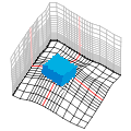
格子内部の物体の設定
Set objects in a grid
計算格子設定ダイアログボックスの属性タブで、
格子内部の建物などの物体を示すレイヤーを指定します。
該当する格子点には物体種別コードが割り当てられます。
In the Grid Settings dialog box, on the Attributes tab,
set layers that represent objects such as buildings inside the grid.
Object type codes are assigned to corresponding grid points.
- [物体レイヤー]
- [Object layers]
物体レイヤーの設定を追加する際は、[追加]をクリックします。
物体レイヤー設定ダイアログボックスが表示されます。
To add an object layer, click [Add],
and the Object Layer Settings dialog box is displayed.
物体レイヤーの設定を編集する際は、
テーブルの編集したい行をダブルクリックするか、行を選択して[編集]をクリックします。
To edit an object layer setting in the table,
double-click on the row, or select the row and click [Edit].
物体レイヤーの設定を削除する際は、
テーブルの削除したい行を選択して[削除]をクリックします。
To delete an object layer setting from the table,
select the row and click [Remove].
物体レイヤーの設定
Object layer settings
物体レイヤー設定ダイアログボックスで、物体レイヤーの設定を編集します。
In the Object Layer Settings dialog box, edit the settings of the object layer.
- [物体レイヤー]
- [Object layer]
対象となる物体レイヤーを選択します。
Select a layer for the object layer.
- [物体判定方法]
- [Object scan method]
各格子点で物体を検出するための走査方法を選択します。
レイヤーの種類によって選択肢が異なります。
Select a scan method to detect objects.
Choices vary depending on the type of layer.
- ポリゴンレイヤーの場合
- For polygon layers
ポリゴンレイヤーのフィーチャはXY平面の2D図形として処理されます。
Z値は無視されます。
Features in a polygon layer are treated as 2D shapes in the XY plane.
Z-values are ignored.
- "押し出し"
- "Extrude"
ポリゴン押し出し図形の最上面が地形に沿わず水平なものとして、物体判定します。
地形が起伏している場合、物体の最上面にあたる格子点のKが
一定にならず、段差ができるかもしれません。
Detect objects assuming that the top surface of an extruded polygon is horizontal and is not along the terrain.
If the terrain is undulating, the K-indexes of grid points for the top surface of the object
may not be the same and steps may be created.
- "押し出し(頂部段差なし)"
- "Along K"
ポリゴン押し出し図形の最上面が地形に沿って起伏するものとして、物体判定します。
物体の最上面にあたる格子点のKは一定になります。
Detect objects assuming that the top surface of an extruded polygon is along the terrain.
the K-indexes of grid points for the top surface of the object will be the same.
- マルチパッチレイヤーの場合
- For multipatch layers
- "簡易判定"
- "Simple"
レイヤー内の各フィーチャが単純な箱型のサーフェスモデルである場合は、この項目を選択します。
Select this item if features in the layer are simple box-shaped surface models.
- "閉じた図形"
- "Solid"
レイヤー内の各フィーチャが完全に閉じたソリッドモデルである場合は、この項目を選択します。
Select this item if features in the layer are solid models completely closed.
- "精細判定"
- "Refine"
"簡易判定"や"閉じた図形"でうまく判定できない場合は、この項目を試してください。
時間をかけて物体判定します。
Try this item if features are not detected well by "Simple" or "Solid".
It takes time to judge objects.
- "三角パッチ"
- "Patches"
レイヤー内の全フィーチャがまとめてひとつの物体を構成する場合は、この項目を選択します。
Select this item if all the features in the layer together make up an object.
- ラスターレイヤーの場合
- For raster layers
- "地上高"
- "Ground Height"
ラスター値が地上高を示す場合は、この項目を選択してください。
Select this item if raster values indicate heights above the ground.
- "物体種別コード"
- "Object Type Code"
ラスター値が物体種別コードを示す場合は、この項目を選択してください。
Select this item if raster values indicate object type codes.
- 鉛直位置設定用フィールド
- Fields for the vertical position
- [地面の標高]
- [Ground elevation]
物体の位置における地面の標高を示すフィールドを選択します。
空欄の場合は、地形レイヤーの標高が適用されます。
マルチパッチ図形のZ座標が絶対座標で設定されている場合は、この項目は空欄にしてください。
Select a field indicating the elevation of the ground at the position of each object.
If it is blank, elevation values of the terrain layer will be applied.
If the Z-coordinates of multipatch shapes are the absolute values, leave this box blank.
- [物体の高さ]
- [Object height]
ポリゴンレイヤーの場合は、物体の高さを示すフィールドを選択します。
マルチパッチレイヤーの場合は、この項目は不要です。
For polygon layers, select a field indicating the height of the object.
For multipatch layers, this item is unnecessary.
- [地面からのオフセット]
- [Offset from the ground]
地面から浮いている物体がある場合、地面からのオフセット距離を示すフィールドを選択します。
マルチパッチ図形のZ座標が絶対座標で設定されている場合は、この項目は空欄にしてください。
If some objects are floating from the ground, select a field indicating the offset distance from the ground.
If the Z-coordinates of multipatch shapes are the absolute values, leave this box blank.
- 物体属性フィールド
- Fields for object attributes
- [物体種別コード]
- [Object type code]
物体種別コードを示す整数フィールドを選択します。
このフィールドが空欄の場合は、フィーチャが存在する格子点には障害物を示すコードが与えられます。
Select an integer field indicating the object type code.
If it is blank, the code representing obstacles is given to grid points where features exist.
- マルチパッチ オプション
- Multipatch options
- [隙間許容サイズ]
- [Gap tolerance]
物体レイヤーがマルチパッチレイヤーで、上下に食い込んで重なっているフィーチャを含む場合、
正常に内外判定できないことがあります。
この項目で、物体が隙間なく重なっていると判定する許容距離を設定します。
If a multipatch layer is selected for the object layer and it includes features overlapping vertically,
it may not be judged inside or outside correctly.
In this box, enter the distance to judge that objects are overlapping without gaps.
- [下方からの検出を省略]
- [Omit detection from below]
レイヤー内のマルチパッチ図形が底面の無いサーフェスモデルである場合は、このチェックボックスをオンにします。
Select this checkbox if multipatch shapes are surface models without bottom surfaces.
- ラスター オプション
- Raster options
- [地上高 デフォルト値]
- [Default ground height]
物体判定方法として"物体種別コード"が選択されている場合に必要です。
ラスター全域に適用する地上高を指定します。
Required when "Object Type Code" is selected as the object scan method.
Enter the ground height to be applied to the entire raster.
- [物体種別コード]
- [Object type code]
物体判定方法として"地上高"が選択されている場合に必要です。
ラスター全域に適用する物体種別コードを選択します。
Required when "Ground Height" is selected as the object scan method.
Select the object type code to be applied to the entire raster.
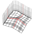
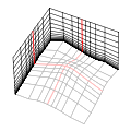
計算格子の表示設定
Display settings for a grid
計算格子設定ダイアログボックスの表示タブで、
計算格子の表示・非表示や配色、シーンに描画する断面を設定します。
In the Grid Settings dialog box, on the Display tab,
specify visibility, color scheme, and the cross-section to draw the computational grid on the scene.
- [格子線を表示]
- [Show grid lines]
シーンに格子線を表示する場合は、このチェックボックスをオンにします。
Select this checkbox to display grid lines on the scene.
- [編集中に鉛直方向の計算を省略する]
- [Simplify vertical coordinate calculation while editing]
格子の設定を変更すると、シーン上でリアルタイムに格子が描画されます。
格子点数が多く表示に時間がかかる場合は、このチェックボックスをオンにすると編集中の格子が簡略化され、表示速度が早くなります。
When changing the settings of the grid, it is drawn on the scene in real-time.
If the number of grid points is large and it takes time to display, select this checkbox to display the editing grid simply and faster.
- 格子線のシンボル
- Grid line symbol
格子線の色などを設定します。
Specify the colors of the grid lines.
- 編集中の格子線のシンボル
- Editing grid line symbol
編集中の格子線の色などを設定します。
Specify the colors of the grid lines you are editing.
- シーンに表示する格子層
- Visible grid index on the scene
シーンに表示する格子の断面の位置を、格子インデックスで指定します。
To change the visible sections of the grid, enter the grid index for each axis.
Copyright (C) 2021 Environmental GIS Laboratory, Co. All rights reserved.